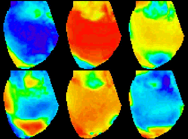
There are 464 photodiode elements
with 464 ouput channels in the array (We guarantee less than
3% defective channels). The fiber-optic array is a perfect hexagonal
pattern of 469 elements. It uses 0.75 mm fiber-optics to couple
individual photodiodes to a hexagonal aperture of 20 mm. At
the image plane the fibers are tightly packed and fill 92.6
percent of the active area. This is significantly higher than
that of monolithic arrays (50 %). The design is discrete which
allowed flexibility in the choice of photo-diodes. This increases
the signal- to-noise ratio in experiments with low light levels
where the dark current of the photodetector becomes a major
source of noise.
Dynamic Range
The array uses optical grade polymethyl
acrylic fiber optics. This fiber consists of an inner acrylic
core and a thin fluorinated cladding. This gives a high Core/Clad
ratio for a large active area of the array aperture. The following
are the properties of the fibers:
| Core: |
Polymethyl Methacrylate |
| Cladding: |
Fluorinated Polymer |
| Fiber
diameter: |
0.030 (0.75 mm) |
| Optical
properties: |
| Spectral
Range: |
400-800 nm |
| Attenuation: |
:<200 db/km @@ 650 nm |
| Refraction
Index: |
Core: 1.492
Clad: 1.417 |
| Numerical
Aperture: |
0.47 |
| Accepting
Angle: |
56o |
|
The optical attenuation of the fiber
is negligible (the distance between aperture and the diodes
is less than 15 cm). An optimum optical coupling has been achieved
by polishing both ends of the optical fibers and coupling the
silicon surface of the diode and the fiber with a thin layer
of optical epoxy.
Electrical Properties
The photodiodes are near perfect photo-electrical
silicon devices. They have a high quantum efficiency (> 0.9),
low dark noise, and very low 1/f noise. Tests have showed that
they contribute no noise to the input end of the I/V converter
cards. The electrical properties of the photodiode are: Sensitivity:
0.5 A/W @ 650 nm Shunt resistance: 20 to 50 G ohms Dark current:
> 5 pA Capacitance: 30 pf
Mechanical Construction
The diode array and all the amplifiers
are housed in a metal case made of 1/4" and 1/8" aluminum,
providing a strong mechanical protection and an excellent electro-magnetic
shielding. The module is 11" x 8" x 13" and weighs
25 lbs. The mother-board in the housing is designed to directly
interface with the preamplifier cards. The housing comes with
a C-mount but adapters for other mounts can be installed by
the customer.
Coupling the H-469III diode array
to the microscope:
With a proper adaptor, the diode array
can be mounted on C-mount port, TV port or any other port with
a real image of a microscope. However, it is recommend that
it be mounted on a "simple" port for a maximum light
throughput. Most research microscopes provide this kind of high
throughput port. The rule of thumb is that the fewer lenses
between objective and the fiber optics, the higher the throughput.
On the housing outside the optical aperture there are four mounting
holes tapped with 10-32 threads for mounting adapters other
than C- mounts. These holes can accept 10-32 screws up to one
inch long. Longer screws may break the seals inside the housing.
The array unit is a heavy load for the microscope and support
only via the image port is not recommended. Additional mechanical
support can be constructed using two threaded 1/4-20 holes on
the back of the housing. Newport optical bench parts can be
attached to the holes.

IMPORTANT PRECAUTIONS
PROTECT THE FIBER
OPTICS APERTURE. DO NOT TOUCH IT. NEVER USE ALCOHOL OR ORGANIC
SOLVENTS TO CLEAN THE APERTURE. The fibers on the aperture
are acrylic plastics. They are softer than glass and can be
scratched by sand, metal and other hard objects. These fibers
are also very sensitive to alcohol and organic solvents. If
they must be cleaned, use lens paper to wipe, and if necessary,
use distilled water and mild detergent. AVOID
EXPOSING THE FIBER OPTICS APERTURE TO UV LIGHT. UV may
shorten the life of the fiber optics. In ordinary fluorescence
microscopes, UV can never reach image ports, unless unusual
modifications were made. If your microscope has been modified
and you use light source with UV light, make sure the array
aperture is not exposed to the UV light. USE
STRONG MECHANICAL SUPPORTING HARDWARE TO SECURE THE ARRAY AND
MICROSCOPE. THE ARRAY IS A HEAVY INSTRUMENT WITH CABLES RUNNING
FROM IT. DO NOT SUPPORT THE ARRAY ONLY BY THE MICROSCOPE.
If array is mounted on top of the microscope, be sure to secure
the microscope on the table. The array needs to have an extra
support in addition to the image port. Two 1/4-20 threaded holes
on the back of the housing can be used to mount Newport standard
optical bench parts for mechanical support.
|
|


